by Adam Maurer, VK4CP
Issue 59 - November 1998
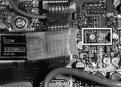
 The main board of the IC706 showing C267
Having taken my IC-706 back to Icom twice for this same fault, I was not prepared to be inconvenienced a third time. Upon checking the previous fault reports I noticed that the ‘FM VCO’ had been tweaked. Hmm… there’s a 9MHz VCO active during FM mode only which is modulated from the mic amp.
Under fault conditions the symptoms are:
very low output power (enough to be heard on a nearby receiver on the shack bench but that’s it);
the carrier frequency is not what the dial indicates, typically 5 - 30kHz low;
the carrier tends to wander and sounds spurious.
I discovered that C267 (a miniature SMT trimmer capacitor located – see picture - 9mm to the right of the 9.0115 MHz IF Filter on the Main Unit) was not re-flowed to the PCB to a satisfactory standard. There was insufficient solder paste applied during the printing process, the end result being an intermittent solder joint and an unlocked 9 MHz VCO.
After re-touching both pins of C267 with fresh solder it’s performed faultlessly since. Although access to the offending area is easy you will need a very fine tip on your iron to get to the pin on the filter side without damaging the cap and disturbing two nearby 0603 chip capacitors.
small phillips-head screwdriver
accurate frequency counter (another receiver will do)
dummy load, power meter and coax patch leads
soldering iron with very fine tip (in good working order!)
fine solder 0.7 or 0.5mm
de-solder wick if required (never ever use a plunger type solder sucker on SMT boards)
1. Turn the transceiver off (der!).
2. Disconnect all leads.
3. Using a phillips-head driver, remove top cover only.
4. With radio upright & front facing towards you (normal operating position), the MAIN unit is the front board.
5. Locate 9.0115 MHz IF filter and then locate C267 (identified on silk-screen)
6. Using fresh solder, carefully re-touch up solder joints to both pins of the trimmer cap. The filter side is difficult due to nearby capacitors and the fact that the ground plane sinks a lot of heat.
7. Inspect the near-by area to double check other suspect solder joints (unlikely, but worth doing).
8. Re-connect the DC power lead.
9. Connect to dummy load via power meter.
10. Turn transceiver on, select FM mode, and select convenient test frequency.
11. Confirm TX carrier frequency is correct against the frequency counter or another receiver.
12. Check that power output is appropriate to the power setting.
13. If all is OK, turn off and replace the top cover.
It is unlikely you will need to tweak C267. The setting is not that critical, just set it in the centre of the lock range.