Chris Patterson, W3CMP - Issue 62, August 1999
Specification of
Commander 50MHz Amplifer
W6JKV's Amplifier
 Figure
1: The combined 2m and 6m 3CX800A7 amplifier used by K5AND & W6JKV from many
exotic locations.
Figure
1: The combined 2m and 6m 3CX800A7 amplifier used by K5AND & W6JKV from many
exotic locations.
This article will document the conversion of a Command Technologies Commander II VHF amplifier RF deck from two to six metres. The conversion results in a compact package which produces 800 - 1000 watts output with 20-25 watts drive.
Command Technologies, of Bryan, Ohio, has produced the Commander II for 13 years. The amplifier uses a single 3CX800 in a stripline configuration, and is conservatively rated at 1000 watts PEP output. Dick Hanson, K5AND has built two of the six metre decks. One has been combined with a custom two- metre RF deck in a DXpedition amplifier which Jimmy Treybig, W6JKV, has used successfully on six metres and two metres, including EME, from several exotic locations (see figure 1).
Although I am not nearly as adventurous as Dick, with the information which follows, I modified another deck which directly bolts into a Commander II chassis. My amp weighs 60 lbs, and although not as easily switched from band to band as Dick’s, allows replacement of one RF deck with another.
At the time these decks were converted, there were no high power compact six metre amplifiers available in the US. Since then, Command Technologies has received type acceptance for and is selling a six-metre amplifier using a single 3CX800 in a slightly larger package.
The circuit diagram of the amplifier is shown in figure 2.
The cathode input circuit is a T-network. It consists of a fixed coil (10 turns #18 enamelled wire, 1/2" diameter X 1" long), a 50-75 pF variable capacitor, and a slug tuned coil. I used 7 turns of #18 wire on a J.W. Miller #4005-2 form (red slug); Dick used 7 turns of #18 on a 1/2" diameter form with a red slug. Instead of the slug-tuned coil, a second identical air-wound coil can be substituted. However, the coil turns may have to be squeezed or spread to achieve a 1:1 VSWR.
Figure2: The circuit diagram of the Commander II
Amplifier
The filament choke is wound on a 5/8" diameter plastic (eg Delrin) rod. Eighteen bifilar (36 total) turns of #16 or #18 enameled wire are wound on the form and covered with epoxy. The plate circuit is a pi-network, which uses the existing 2-30 pF plate tuning capacitor and part of the stripline. An air-variable capacitor with receive spacing of 100 - 200 pF replaces the loading capacitor. A 100 pF 5 kV transmitting doorknob is paralleled to the loading cap to achieve the necessary circuit capacitance.
The plate coil is 6 1/2 (or so) turns of 1/8" tubing or #8 wire, 3/4" in diameter, 1 5/8" long mounted between and parallel to the tuning and loading capacitors.
The plate choke is made from a 2 1/2" piece of 1/2" diameter Teflon rod. Two holes are drilled through the rod, 1 7/16" apart. The top hole is 5/16" below the top of the rod. Forty turns of #22 enamelled wire are close wound on the rod, and affixed to 4-40 brass screws which pass through the holes. The bottom end is also threaded so it can be mounted vertically on the chassis.
To modify an existing Commander II, first remove the RF deck from the chassis. The blower and RF deck are removed as a unit. The blower leads must be unsoldered to pass through the chassis.
After the deck is removed, take out the tube and unscrew the back wall holding the blower and the side-wall opposite the HV and RF connectors for access. Next, remove the input circuit components and filament choke. The input tuning capacitor must be unsoldered from its mounting bracket.
Once the cathode components are removed, remove the plate choke, stripline, output link and loading capacitor, tube collar, and plate blocking capacitor. Before removing the stripline, mark it where the left edge of the piston capacitor contacts it.
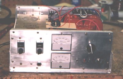
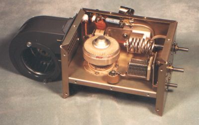 Figure3
: Top view of the Commander II RF deck
Figure3
: Top view of the Commander II RF deck
Before modifying the RF deck, examine figures 3 and 4 and determine how you will fit the parts. ‘Dry’ fitting the parts is a good idea.
Prepare the RF deck and stripline as follows:
Replace the screw-in UHF connector with a flanged SO-239
connector. Mount ground lugs as necessary on the mounting screws.
Drill a hole for the input tuning coil form halfway between
the RF input jack and the filament/bias cathode terminal strip (omit if you
are using an air wound coil).
Drill a hole for the plate choke. This hole is 3/4"
from the back wall and 1" from the side-wall containing the HV jack. It
should be only large enough to let the plate choke mounting screw extend
through the chassis and thread into the choke body. Note: Before
drilling this hole, test fit the choke body to make sure there is adequate
space between the tube collar, choke, HV jack and the back and side walls.
Some tube collar stems vary in length.
Cut the plate stripline 1/4 - 3/8" beyond the edge of
the piston capacitor and then drill a hole for a 6-32 screw along the edge
to attach to the hot end of the plate coil. Note: If the stock
reduction drives and loading capacitor mounting bracket are used, there is
less room between the piston (plate tuning) capacitor than Dick had. I
drilled the hole for the screw in the triangular area between the upper
corner of the stripline and the piston cap. Dick drilled his in the center
of the stripline.
Remount the stripline, using the mark drawn earlier as a
guide.
Install a 150-200 pF (maximum) loading capacitor. If the
existing mounting bracket, is used, cut the shaft to the same length as the
original loading cap. Make sure there is adequate clearance for the plate
coil when the loading capacitor is tuned through its entire range.
Drill hole for doorknob capacitor which is paralleled to the loading capacitor cap. The exact location is not critical. (Dick mounted his on the side-wall; I mounted mine on the deck behind the loading cap).
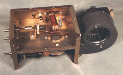 Figure
4: Bottom view of the Commander II RF deck
Figure
4: Bottom view of the Commander II RF deck
Mount the new components as follows:
3 x 0.001 600V bypass caps on the filament/cathode
terminal strip.
Cathode choke (RFC-2) - Ohmite Z-50 or J.W. Miller 7-10
µH, or wind one per the ARRL VHF/UHF manual.
Filament choke (RFC-3) and T-network (coils and air
variable capacitor (C-1) 50-75 pF max.) Air-wound coils (L2-3) are 10 turns
of #18 enamelled wire, 1/2" diameter 1" long.
1000 pF 500V silver mica coupling cap between T-network
and RF input jack.
Plate choke (RFC-1) and stripline blocking cap (C-5)
100-500pF, 5 kV.
Plate coil (L-l).
Output choke (RFC-4) - Ohmite Z-50, or home-made.
Plate load doorknob capacitor (C-4) - 100 pF, 5kV.
RF output lead – RG-142 from loading cap to output SO-239. Ground shield by soldering to ground lug at a connector mounting screw.
When all components are mounted, reassemble the RF deck and reinstall the tube. Open the input tuning and loading capacitors to half way, and tune up the deck. The T-network input coil and plate coil will most likely have to be spread or squeezed to achieve resonance.
After the amplifier is tuned, the operating parameters should be close to this:
|
Drive: |
25 watts |
|
Power Input: |
1500 watts |
|
Power Output: |
1000 watts |
|
Grid Current: |
20-30ma |
|
Plate current: |
600 ma (max) |
|
Plate voltage: |
2500 (approximate) |
|
Idling Current: |
70 ma |
You may e-mail or phone Dick or me at K5AND@ga.prestige.net or (770) 844-7002; or W3CMP@aol.com or (717) 569-3828.