Dennis, PA7FM and Peter, PA2VST
Issue 65, May 2000
 Theo, PA3HEN/MM on the air
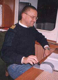
For those who like grid-square hunting, PA3HEN/MM is probably a well-known callsign. Here’s the story of Theo, who is the captain of a cargo-ship and is regularly active from ‘wet’ squares on six metres.
It all started about two years ago, when Theo was active as PE1RNI/MM from several squares around Europe. He came in contact with PA3BLS (now his QSL manager) who made him enthusiastic about six metres. After passing the CW exam, Theo became PA3HEN. His first QSO on six metres as a /MM station was with ON8MC from IM49 on 1st May 1998, about two years ago now.
Theo doesn’t sail on the same route on every trip he makes; he has to wait to find out where the cargo will be and where to take it to, so he’s active from new squares all the time. But plans all the routes himself, which allows him to have a good look at the map to see what squares are ‘wet’ or not - being the captain of the ship makes it easier to change the course.
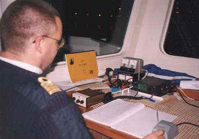 The PA3HEN/MM rig
Off course he’s making money for his company so it’s impossible to make the trip longer to activate a rare grid. But sometimes it’s very easy, like grids IN42, IN41 IN40, IM49 by just sailing a couple of hundred metres more to the west, instead of the originally planned route more to the east (IN52, IN51...).
During the first trips he was only using a dipole and low power from his IC706 because the power supply was too small. He needed a better lightweight power supply as he flies to various countries to get onto his ship after a few weeks off work. Now he uses a lightweight, switched-mode power supply, easy to take on the plane together with his transceiver and antenna.
The antenna
One other problem was the dipole antenna. It was too directional and gave problems on SWR during bad weather - not too good for working DX on six metres. So he needed a better antenna and asked Peter, PA2VST to design one.
This was not an easy job, as the antenna needed to have some specific characteristics:
• all-round radiation pattern
• >0 dB gain
• light weight
• elements a maximum of 1.20 m long (because of transport)
• mechanically strong
• low Q-factor because of surround- ing objects
• easy to set up.
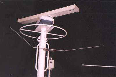 The omni-directional dipole antenna designed for Theo by Pere, PA2VST. Note the radar antennas in close proximity.
You see, not too easy! How was it going to be possible to make an antenna with gain, short elements and a low Q? One option would have been a vertical collinear, but horizontal polarisation would be better on six metres. A horizontal collinear would give mechanical problems and would have elements that were too long.
So a dipole it should be, but a dipole with a round radiation pattern. In Peter’s early days as a radio amateur he used to work mobile on two metres with a specially-made dipole with a more or less round radiation pattern.
For designing antennas, Peter mainly uses computer programs based on NEC and Mininec. In this way it was possible to try out some antennas without a lot of mechanical work; easy from a lazy chair!
Peter’s first try was a round folded dipole. In the ‘Antenna Engineering Handbook’ of Johnson & Jasik, it is predicted that all energy would be radiated straight up. He tried to get a more horizontal radiation pattern by adding a reflector to the dipole, but the results were not really good.
It appeared that the bigger the hole in the ring, the better the radiation pattern. An even better pattern occurred when he unfolded the end of the dipole; he optimised the idea and a more or less ‘round’ radiation pattern appeared. Making the first part of the antenna thicker allowed two of the requirements to be met: easy construction and short elements.
From further computer modelling it appeared the antenna radiated in all directions, including horizontally. How to lower the vertical components and get some gain? Quite easy: make sure you have a good ground underneath the antenna. A yagi also gives more gain - about 3 dB under the best circumstances.
With the dipole Peter developed there is a compromise between the all-round radiating effect, low Q and as much ‘ground-gain’ as possible. ‘Ground-gain’ on Theo’s ship is easy. The antenna is just a few metres above the steel of the ship and there is a lot of water next to that - all ingredients for a good radiation pattern. But it is also very important that the radiation pattern of the antenna is not effected by the radar antennas of radar on the ship, hence the need for a low Q.
After remodelling the antenna with available materials it needed some adjustments, but after solving some small problems it was time to get a real antenna instead of the still virtual computer model.
The dipole is made of two massive round pieces of aluminium, 44cm long and 19mm in diameter. On each end there is a 105-cm long, 10-mm diameter round piece fixed at an angle of 130 degrees. A friend, PE1PZF was able to make some holes at the right angle at his QRL, so that just a bolt would be enough to get some mechanical stability. The two 19-mm pieces were mounted together on a plate that could be mounted on the mast with some clamps. With an impedance of 52 Ohms, the coaxial cable was easily attached to the dipole using a ’bazooka’ balun.
After completing the construction it was time for some tests. The antenna on a small tower gave some nice results, SWR 1:1.2 and resonance at 50.150 MHz. Later, on a higher tower, the same results were found. Compared to a five-element yagi, signals were generally about one s-point lower on the dipole, but nearby stations from EH1 and F (short-skip Es from PA) were much louder on the dipole, because of the big vertical component of the dipole compared to the yagi.
After some last tests the antenna was given to Theo, who used it in the garden at home for a couple of weeks. He found out the antenna really did work OK, and during the next trip he used the antenna.
Using the new aerial, Theo worked many countries from many grids. He made over 1000 QSOs: mainly into Europe but from the Mediterranean he also worked into PY, LU, 7Q, CX and even DX some of us are still only dreaming of like HC and VY.
This summer, Theo will be around Europe again. If you hear him, give him a call: he might be in a new square for you.
The PA3HEN/MM QSL manager is PA3BLS, either direct or via the PA QSL bureau.