Andy Kissack, GD0TEP
Issue, 56 February 1998
A few months ago Andy, GDŘTEP made the first six metre EME QSO from the Isle of Man by contacting Bob, K6QXY. In this article he describes the equipment that he and Bob were using.GDŘTEP
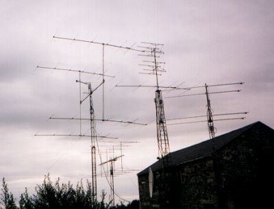 A positive jungle of antennas!
The antenna system is four by seven elements, these being stock Create antennas. The system is designed as a temporary set-up as there isn’t enough room for it all the time, nor would it stand our winter!
The ‘H’ frame is simply three 2" thick-wall scaffold tubes bolted together with some steel wire for bracing (this is one area that still requires more thought). Elevation is by a 36" screw jack dish actuator with a 200-position controller, set up with each position as one degree. The rotator is a Yaesu SDX1000. The phasing for each antenna is done with four equal lengths of 50ohm coax, then two Ľ sections into a common T. This was attached to my mast head pre-amp with switching for transmit and receive lines. The feeders are LDF-450 for TX and Westflex 103 for RX, and the masthead pre-amp is a home brew device.
The rig is the Yaesu FT-650 with a Datong FL2 audio filter in the speaker line, and the PA is an amplifier from Linear Amp UK. Moon tracking is by VK3UM’s excellent software.
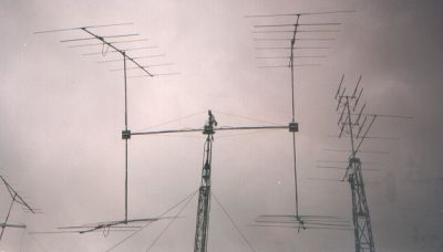 Looking
Through GD0TEP's 6n EME Antenna System
Looking
Through GD0TEP's 6n EME Antenna System
This all sounds simple enough but it does take some ‘getting together’. And, even though at the time of my sked with Bob K6QXY it was still summer, there was a small gale the same day that damaged the tower sufficiently enough to make me call off my next sked with Mike K6MYC from M-squared.
As soon as the tower is repaired I’ll be setting up another sked with Mike, I just hope it’s soon, before the real winter sets upon us.
The sked itself was interesting. It was 05.00 UTC so I was still half asleep, and when switching everything on I managed to blow the pre-amp with two minutes to go before the sked. I decided to try with out it by listening up the TX line. Fortunately it worked.
K6QXY
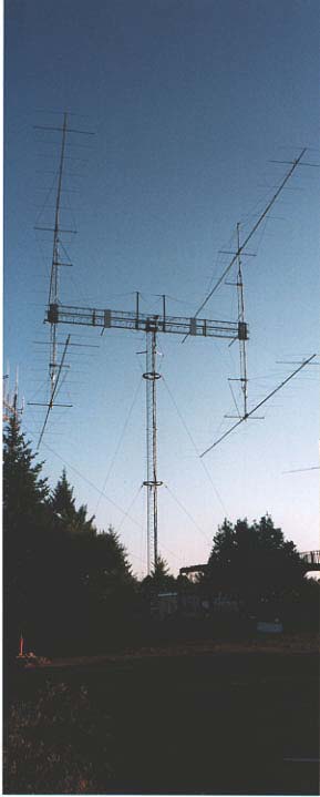 K6QXY's EME Array
In the K6QXY-WA6MXI EME array, the tower assembly consists of 50 feet of "TRI-EX T-20" with a face width of 18 inches. Two rotating guy ring assemblies are used, one at the 20 foot level and the second at the 40 foot level. The tower sits on a combination of a 3 inch vertical and 2 inch horizontal thrust bearings. Tower rotation is accomplished via a 3:1, #100 chain drive and gears coupled to a 3,600:1 gear box. Power to turn the gear box comes from a Ľ horsepower, 1750 rpm, reversible AC motor. The final rotation speed is one revolution every six minutes. Azimuth read-out is accomplished utilising a magnet and magnetic reed switch attached to the AC motor shaft. Generated pulses are feed to an M-squared model RC-2800 controller. The resolution obtained by this method is better than one degree.
Elevation is obtained by the use of a home-brewed ‘pivot over centre’ design which maintains all loads, as closely as is possible, directly over the vertical centre line of the rotating tower. The ‘H’ frame assembly is supported by a solid two inch axle, captured on each end by a pillow block bearing with lateral thrust rating of 10,000 pounds. The entire ‘H’ frame, its vertical towers and antennas are elevated using a heavy duty, commercial grade, 24 inch throw, one inch diameter, Acme thread, re-circulating ball nut, 28 volt DC linear actuator. The elevation readout is accomplished using a US Digital corporation, model T-2, electro-optical inclinometer. Pulses from the inclinometer provide position information to the M-squared RC-2800 controller. Our elevation resolution is better than ˝ degree. We are able to elevate the antennas through an arc of -2 degrees to +90 degrees.
The ‘H’ frame itself consists of two, 40 foot long, parallel sections of Rohn model 45-G tower. Strapped together with a series of fabricated hot dipped galvanised bracket assemblies, the tower sections form a relatively twist free horizontal member. The vertical towers are Rohn, model 25-G. There are several trussing cables using "Dracon" rope with turnbuckles to tension them. Additional horizontal tubing braces were used, fabricated from 1 ˝ inch, thin wall, ASTM galvanised steel pipe as used by the fire sprinkler industry. This material has a very attractive weight to strength ratio.
The physical design allows us to climb to just about any place on the array. By elevating to +90 degrees, all four antenna driven elements are accessible using a rolling ladder or boom truck. During periods of non-use the array is placed in a ‘parked position’, its base locked down and the ends of the Rohn 45-G ‘H’ frame tethered in three directions. Our design parameters were 100 MPH wind survival... it has surpassed these parameters, surviving 120 MPH!
Currently the 50MHz yagis are 13 elements, 3.0 wavelength, special heavy duty boom, custom produced for us by M-squared. Stacking dimensions are 37 feet horizontally and 35 feet vertically. This is the optimum spacing for best G/T. Each antenna is phase- matched with Times Microwave LMR-600 cable going to a four port "Air divider". The estimated overall system gain is 19.7 dBd
The TX/RX feedline is 15/8 heliax from the station to the tower base, then 1 Ľ heliax up the tower to the four-port power divider. Rotation end elevation loops are LMR-600, utilising 7/16 Din connectors where possible. The total TX/RX cable loss is under 0.5 dB.
The transmit signal is generated with an Icom 551-D driving a pair of 8877’s in parallel. The receive signal is processed through an angle linear, 15 dB pre-amp ahead of a receive converter fed into a TS-930S at 28MHz. Various outboard DSP filters are also used.
All keying circuits are sequenced using an Angle linear sequencer and no relays are keyed hot.