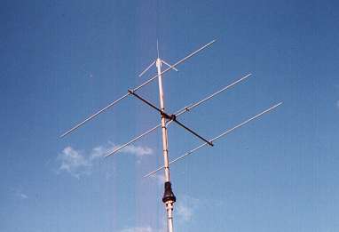
 The G8VR small antenna, with a 2m packet antenna above it
The G8VR Small Yagi was first described in Practical Wireless for July 1989 with further information appearing in a later edition. In August 1996, issue 50 of Six News carried an updated version of both articles.
There were certain errors and omissions in the original published article, which should by now have been corrected. Dozens of these antennas have been built around the world, and despite the fact that I introduced it some ten years ago, I still receive five or six requests for information every year. It has become obvious that not all potential builders are in possession of all the relevant information, so these notes may clarify some of the points which have emerged.
Early in the last solar cycle (No. 22) I was using a simple 50 MHz half-wave dipole, which proved to be no match for the long yagis that were beginning to appear. Being somewhat restrained by local conditions, I needed a small antenna which would sit easily on my extendable mast (which is disguised as a drain pipe and fixed to the rear of the house) and not look too much out of place among television and FM aerials in the area. Obviously I wanted it to have some forward gain but I was convinced that an antenna providing low-angle radiation would be more telling when chasing the exciting DX appearing on the new band.
After much delving into the literature, plus a certain amount of experimentation, I settled on a three-element yagi with a boom-length under six feet. It turned out well, for using this antenna I had worked 110 countries by the end of Cycle 22, including three UK firsts. The following notes are based largely on queries raised by operators who are building or have completed a yagi to this design. Many of them had never previously attempted to construct an antenna of any type, and therefore they were unsure of the effect on performance of small (and sometimes large!) changes that they had introduced into the original design.
Dimensions
My original text gave all dimensions in inches. The draughtsman at PW, no doubt following that magazines standards for metrification, converted everything into millimetres and included one gross error in the spacing between holes in the shorting strap. In my other hobby, building steam locomotives, cutting metal to an accuracy of a millimetre is not considered a great problem. However hacksawing a length of aluminium tubing on the kitchen table to a final length of 2921mm, as the article suggests, sounds tricky and hints at a need for extreme accuracy!
My dimensions, restored to their original form, make the job seem less daunting:
|
Reflector length |
9ft 7Ẅins |
|
Driven element length |
9ft 3ins |
|
Director length |
8ft 10Ẅinss |
|
Element diameter (O/D) |
5/8 inch |
|
Element spacing |
2ft 10Ẅ ins |
|
Gamma bar length |
12 ins (see later) |
|
Gamma bar diameter
(I/D) |
0.3inch |
|
Shorting bar spacing |
21/8 ins centres |
Matching
A match can be achieved over a reasonably wide range of gamma-bar length/capacity variations. Although the gamma-bar length is shown as 12 inches, it is intended that the shorting bar should be used trombone fashion, sliding along the driven element to find the best length for matching before tightening the setscrews. In my case I obtained a match with a gamma bar of length 10ỳ inches, measured from the SO239 socket to the open end of the shorting bar. The remaining bit sticks out of the open end of the shorting bar. Purists may prefer to cut it off flush, though if you do, check again to be sure that it hasnt affected the matching appreciably. In my case the co-ax inner (from a length of RG8/U) occupies the entire length of the gamma bar.
Pushing in lengths of co-ax inner, soldering to the SO239 and erecting the antenna only to find that the match is poor and the whole thing has to be taken down again can be a chore if you dont hit a near-match immediately. Pointing the antenna skywards to avoid reflections from nearby objects can be a great help.
A much more elegant method of achieving a gamma-match is possible if you have some means of measuring capacity. In this case, with no co-ax inner inserted into the gamma bar, a variable capacitor is connected between the SO239 spigot and the open end of the gamma bar (the end inside the plastic box). The capacitor is adjusted for lowest SWR then carefully removed and its value measured. Using the gamma bar, a co-ax capacitor can then be made up to the same value. Alternatively the co-ax capacitor system can be abandoned in favour of using a fixed capacitor of the correct value inserted permanently.
In a much earlier solar cycle, before we had 50MHz in the UK, I matched a 28MHz yagi using this method, inserting a silver mica capacitor of the correct value. When protected from the weather by a small box, it gave no trouble over several years. If the required value is low enough, a small air-spaced trimmer with vane spacing sufficient to cope with the RF voltages encountered will be even better. Whichever method is adopted it is a good idea to seal the open end of the gamma bar against the weather.
The way in which a yagi is built can affect its characteristics. This little antenna is of the plumbers delight variety, so all elements are connected directly to the boom and the outer conductor of the feeder line is also joined to the boom (centre of driven element). Insulating the elements from the boom, or using a non-conducting boom as some constructors have done, will change the characteristics of this antenna noticeably; although there is little doubt it can still be matched in the way described, the dimensions quoted may no longer apply.
Some builders have preferred square section tubing for the boom (eg ZS6CE, G7TUA). This is attractive because the elements can be bolted directly to a flat face; ZS6CE achieved an SWR of between 1.1 and 1.5 over a range of 50.1 to 50.4MHz with his demountable square-tube version.
Others have made elements from two sizes of tubing, with a telescopic fit to produce what is effectively a tapered element. Again, these are perfectly good ways of building a yagi but the feed impedance may differ from the model that I built, though a 12-inch gamma bar should accommodate these changes.
Computer Simulations
As mentioned in the earlier articles, computer simulations based on the dimensions of my yagi suggested that (a) it resonates rather higher in frequency than I had designed it for, and (b) changes in element lengths/spacings can improve its performance. The simulations suggested the following dimensions for the yagi:
|
Reflector length: |
Increase by 3.3 inches |
|
Driven element: |
No change |
|
Director length: |
Reduce by 1 inch |
|
Spacing reflector to driven element 2: |
2 inches |
|
Spacing director to driven element: |
44.3 inches |
Its somewhat strange that the driven element requires no change yet is reputed to resonate at a rather higher than intended. However, implementing these changes would, the computer said, give an increase in the forward gain of the antenna from 5.7 to 6.0 dB. I would be happy to place a small bet that if a group of people all built antennas exactly to my specification, there would be a spread of measured gain figures well in excess of 0.3 dB due simply to minor constructional factors.
It should be noted, too, that after the computer simulations were carried out, no yagis were ever built to the optimised dimensions in order to check their validity. This has had its repercussions, since two American operators who have been corresponding with me both decided to build the simulated version only to find that they could not get a match using my dimensions. Rarely will a good match be obtained first-try by slavishly copying my gamma-bar dimension.
Conclusion
I like this antenna the way I built it because the feed point is at the top of the mast with the director and reflector equidistant from it, resulting in a nice mechanically balanced system. My little yagi has served me well. Of course I would like to hear signals via a seven-element on a 45-foot tower, but in my location this must always be the stuff that dreams are made of.
I can only hope that the emergence, since the last solar cycle, of so many stations in this small island using vast ERPs on 50 MHz will not ruin a truly magic band, giving the small station little chance of penetrating a solid wall of noise greeting the arrival of a rare prefix. But then Im a dreamer. In 1938 I worked into areas such as Haiti, China, Peru and New Zealand on 40 metres using a one-valve transmitter, a two-valve receiver and a length of wire for an antenna!
Drop me a line on e-mail at g8vr@aol.com if I can be of any help.