As I am an engineer myself, I am always looking for simple solutions to sometimes difficult or expensive problems. The often noisy days on six metres make me stay around the shack with the receiver scanning those nice PC birdies all the time!
With WSJT, the FSK441 encoder and decoder software of K1JT, a great new tool for lots of fun is available for all the sixers that are interested in meteor scatter (see box). 50 MHz is by far the best band to operate this mode. Whatever the time of day, you will have reflections introduced by meteors entering the Earth's atmosphere.
As I saw quite a few spots for WSJT on the DXclusters, I wanted to know what it was and how it would behave. I soon found out it is easy to set it up and operate it on the PC. I do not want to give a description on the program itself; you can find lots of descriptions and comments about the software on the net.
Running the software on the PC is an easy job, but interfacing it with your rig is quite another story. Because the PC with WSJT on it will operate your transceiver, some connections have to be made. AF from the set (RX audio) has to be fed to the PC and AF from the PC has to be feed to the rig (TX audio). So as you can see you will need a soundcard in your birdie monster (your computer)! Also your PC will take control for transmit and receive, so the PTT of your mike should be connected to your PC, using your COM port. These are the only things you need to do.
I don't know how your rig is connected to all the other equipment in your shack, but in my situation all equipment is connected to some kind of accessory. This can be a tape recorder, a keyer switch, a TNC, relays or preamps. Also all my equipment is connected to the mains safety earth.
If you are dealing with electronics in the audio-visual world you will recognise the exciting problems of earth loops. Because of all kinds of currents conducting on those earth terminals and interconnections between different kinds of equipment, you have a big chance of hum. I can tell you, I had a fantastic hum on my microphone input - much higher in level than my soundcard could ever generate. This nice mixture of 50 and 100 Hz hum spoiled the first tests and it soon turned out I had to isolate the items of equipment from each other.
I started by isolating the audio between the PC and the transceiver using audio transformers. The ones I used were the professional broadcast types. These are very expensive when you need to buy them, but fortunately for me I always save bits and pieces from former companies I worked for.
But there are much cheaper ways to get a good transformer. In most modems you will find transformers to isolate the modem from the telephone line. So get some of these old modems on the local flea market and remove the transformers from the card. The transformer is not a critical component. Your transceiver probably has a high impedance input and your soundcard a low output impedance. If you have difficulty getting a decent LF level, swap primary and secondary windings. You will need a second transformer for the AF output from your rig to the PC's soundcard line input. See figure 1.
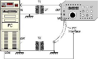
Figure 1: The use of audio transformers to reduce hum.
By doing this I got rid of the big hum. When I measured the level with an
oscilloscope I measured levels up to 60 volts, which can destroy your soundcard
and your rig. So some care is required in connecting PCs and other equipment.
These levels are often introduced through the little capacitors from the mains line to
the common earth in all kinds of equipment. With a little load, the levels will drop
to much safer levels. But don't take chances.
Even after this I still experienced some hum on my AF. This was introduced by the little earth loop that was created by the PTT connection. As you might have seen the PTT of your rig is switching to earth, so the rig earth and PC earth are still connected. I wanted to isolate this from the rig as well, but this can't be done by a transformer. So I had the options of either a relay or an optocoupler. Because relays can introduce some delays and need some current for the coil, I decided to use a more `state of the art' device.
So I choose the optocoupler; the one I found in the files was a CNY21. This optocoupler doesn't require a bias or threshold level on the transistor's base. So you only have four pins on the DIL16 package, which fits easily in a 9-pin D-connector case. Have a look at figure 2. This is really all you need to interface the PTT of your rig to the PC! The pin numbers (4&5) are the pins of your 9-pin D connector for the COM port on your computer.
With this set-up I had quite a few QSOs with clean audio and safe keying of the rig.
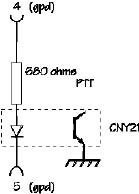 Figure 2: The CNY21 optocoupler.
As WSJT is not used by many operators on Six yet, I was looking for
stations on two metres. I don't have a DX set up on 144 MHz any more, but with a
small antenna you are still able to work MS. So I tried to key my IC706 with the interface
I made.
It worked very well on the IC736 and the IC756 but did not activate the PTT on my 706. I soon discovered that the PTT line was not fully switched to ground because of the CE barrier of the CNY21. Pity, but I needed to solve this and I did not want to go for a relay again. So I choose an extra transistor.
In the IC706 and I guess in most modern transceivers nowadays you will have an 8 volt supply at the microphone connector. I used this to feed the little circuit in figure 3. If you like you can still fit it in a D connector case. I mounted the PNP transistor, 22K and 1K8 resistor in a little box at the IC706 connector.
By the way, this microphone connector is a very cheap UTP network
connector, so ask one of your fellow hams, friends or maintenance people at QRL who
are working with network cables for some used and rejected cables. By cutting
the cable at 10 cm from the connector you are able to create a breakout cable for
your 706 - Icom charge you much more! The connections are as described in
your manual but be careful you don't short-circuit the 8 volts because this will burn the little SMD resistor inside. It will take a
lot of effort to get this one replaced.
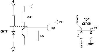
Figure 3: A practical switching circuit for the IC706.
I guess the circuit is simple and easy to use for most commercial transceivers.
I hope you will have at least the same fun building it and working one of the
active stations on Six with it. Whenever you need more info just drop me a note or an
e-mail.
WHAT IS WSJT?
WSJT is the name of a computer program. It stands for "Weak
Signal communications, by K1JT" and it was developed by Joe Taylor, K1JT.
Plans call for the program to include more than one communication mode.
The first mode implemented, and the one that has given WSJT its wide popularity, is called FSK441. It is designed for high-speed meteor scatter communication using `pings' reflected from the underdense ionisation trails of random meteors at approximately 100km height. Such pings are typically a few dB above the noise and last for anywhere from ten to a few hundred milliseconds. WSJT makes QSOs possible in the amateur VHF bands, over typical distances of 500 to 1400 miles (800 to 2200km), using these brief pings. Such QSOs can be successful with modest equipment and without waiting for `band openings'.
WSJT is designed for computers running the Windows operating system; Windows 95, 98, ME and 2000 have all been used successfully. The program sends messages using four-tone frequency shift keying at 441 baud. The name of the transmission mode is FSK441 although most people are just calling it `the WSJT mode'.
FSK441 makes very effective use of the audio bandwidth of modern SSB transceivers. As implemented in WSJT, it generates a clean transmitted spectrum. Each character in a normal text message requires three tones that are sent sequentially. The transmission speed is 147 characters per second, or 8820 letters per minute.
Unlike high-speed CW, which has also been widely used for meteor scatter communications, WSJT does not require the user to play back received `pings' and decode the message by ear. Instead, the decoded text appears in a scrolling window on the computer screen.
WSJT is available for download free of charge at http://pulsar.princeton.edu/~joe/K1JT