

home > archive > the history of 6m > 50 years of 50 MHz part 3

Thanks to all of our authors since 1982!
50 Years of 50 MHz Part 3 - Ken Willis, G8VR |
|
|
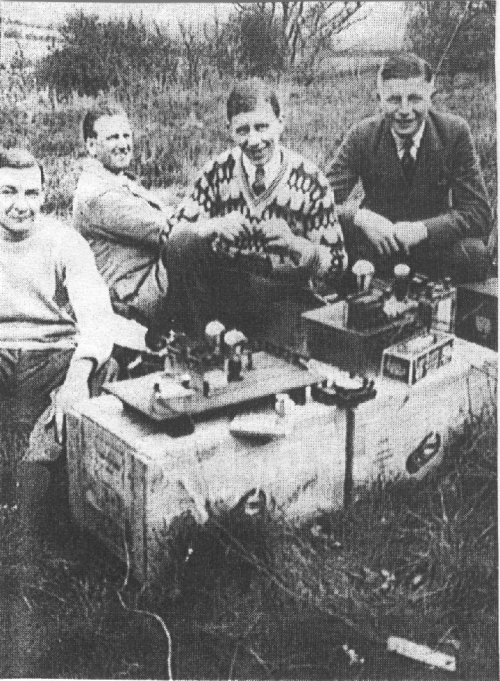
It would probably be fair to assume that the sun has been going through peaks of increased activity at intervals of every 11 years or so (which we now call solar cycles) for the past several million years, but in cosmological terms it was only very recently that the technology to recognise and exploit the situation became available. If we attempt to pick a date when the ‘The Magic Band’ came into being, then it is probably safe to say that it originated from early experimental work by amateurs in the late 1920s or early 1930s, by which time ‘the wireless’ had developed to the point where valves and components were becoming available to the general public. Amateur radio was already alive and well, and inevitably among its ranks were some who were prepared to spend many hours trying to probe beyond the perceived horizons such as attempting to extend the upper frequency at which available equipment could be induced to operate. By the 1930s it was beginning to be understood that radio propagation at frequencies above 30 MHz could be much affected by the sun. The word ‘ionosphere’ had not yet entered the language, but the 1931 edition of the very comprehensive Admiralty Handbook of Wireless Telegraphy, a classic text-book of its kind at the time, refers to a part of the earth’s atmosphere known as the Kennelly-Heaviside Layer, within which, it says, “there is ionisation mainly due to free electrons..…its cause still obscure”. Apart from noting that this layer seems to have some effect on the refraction of electromagnetic waves, the text accepts the conventional theory of the period, that there must be some intangible thing, ‘the aether’, permeating all space, since the propagation of electromagnetic waves over long distances with no apparent medium to conduct them would seem to contradict the laws of physics. This, more or less, was the extent of knowledge of the earth’s upper atmosphere at the time. Keen amateur experimenters, uninhibited by or unaware of any influence of the sun’s radiation, pressed on regardless. In 1929, G2OD had already contacted American stations on the 28 MHz band. Without denigrating this achievement, but with the advantage of hindsight, we could surmise that he was probably lucky enough to catch a time when what we now call ‘the solar flux’ was at a high level. In fact my records suggest that it would most likely to have been on a date just after the peak of Cycle 16, certainly not an outstanding one by 1980-82 standards. To digress, I recall my own amazement, one autumn afternoon in the late 1930s soon after I had left school, to find, on my home-brew 3-valve receiver, a ten-metre band full of very strong USA amateur stations, and this on a band previously filled only with white noise. With so much less known about radio communication in those days, we were often surprised by such moments of apparent ‘magic’, unlike today when everything is analysed and quantified. In the early 1930s British amateurs held an allocation at 56 MHz, known as the ‘Five Metre’ band. Attempts to use the band hit several problems due to the limitations of available components, particularly valves, since the emphasis on development and production favoured parts for broadcast receivers and audio amplifiers. Early experimenters commenced operation on the five metre band using self-excited oscillators with valves designed for much lower frequencies. They proved to be not very frequency-stable. To combat this, early receivers were super-regenerative, this type of receiver having the advantage of being very wide-band. By now, on rare occasions, stations had managed to communicate over ranges of 100 miles on this wavelength, though any contact over more than 10 miles was deemed to be worthy of a report. A typical transmitter would be a pair of triode valves in a push-pull, tuned anode, with a resonant grid circuit and modulated by a suitable audio amplifier. Sometimes the transmitter would be fed from raw AC so that its carrier was easily detectable without speech-generated audio being superimposed, and that often sufficed because these high frequencies were so very exciting to the experimenters, it was enough simply to know that they had heard something identifiable. Co-axial cable had yet to become available; long-wire aerials or dipoles fed with open wire feeders or even twisted flex were the norm. G2XC reported how he and G6NZ, located only a few miles apart but separated by Portsdown Hill near Portsmouth, spent many hours on the five metre band trying to hear one another through this obstacle. When it proved impossible they persuaded a neighbour to drive one of them around the area in his car with suitable equipment on board, so that they could plot positions where reception was favourable. G2XC even copied G6NZ when he was transmitting from a moving bus! All over the country, small groups of enthusiasts were following much the same pattern, going out into the countryside with portable equipment to seek out the high points. In fact it proved so popular in the south, that one Sunday each month was nominated as a field day. Figure 1 shows a typical group. The push-pull transmitting valves (and in this case a push-pull modulator on a separate base) are clearly visible, together with the wide-spaced open-wire feeders using wooden spacers, often impregnated by being dropped into boiling paraffin wax. Note the useful soap-box tables (whatever happened to soap-boxes, those versatile and essential features of my boyhood?).
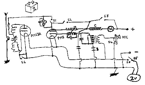
When next you come to switch on your transceiver, take a moment to marvel at the modern technology that, in a very small box, can provide 100-watt multimode multi-band capability. Don’t forget, too, that when you flick the dial to settle on a frequency to within a fraction of a kHz, you’ll expect the rig to stay there. Then spare a thought for a state-of-the-art five metre transceiver of the 1930s. Figure 2 is the circuit of one built by G6NZ, which used just two valves and no doubt was what he was using when he transmitted to G2XC from a bus. G6NZ's 1933 design for half-watt 56MHz transmitter/receiver, from his original drawing. This circuit has some historic significance since it was drawn by G6NZ himself, part of his 1933 comprehensive paper “A Qualitative Investigation of the 56 Mc/s (sic) Ultra Short Wave Band”. Only if you are very elderly might you recognise it immediately as a super-regenerative transmitter/receiver (the word ‘transceiver’ did not come into use until very much later). The PM2DX valve has a dual purpose, it serves as a quenched detector for receiving and as a free-running Colpitts oscillator when transmitting. The PM2 stage is clearly an audio amplifier with carbon microphone input via a transformer. One of its functions is to amplitude-modulate the PM2DX using so-called ‘choke’ modulation, achieved by inserting the LF choke C in the high-tension supply line to both valves. This is quite straightforward. However the coupled inductive circuits between the grid and anode of the modulator valve show that it was also used to generate an ultra-sonic frequency to quench the detector, giving rise to the pronounced no-signal “hiss” experienced when using this type of circuit. In super-regenerative detector / oscillator circuits the value of the resistor between grid and ground can determine whether the valve oscillates freely or is self-quenched. I used a simpler version of the circuit a few years later (“Approximately Six Metres”, Six News January 1994), with a switch in the S6 position of G6NZ’s circuit to allow a megohm or two to be added to the ‘grid-leak’. This caused the valve to switch from being a free-running oscillator to a self-quenched detector. For anyone wanting to do a little circuit-tracing, G6NZ’s own notes state that “For RX: S1 open, S2 open, S3 closed S4 open. For TX: S1 closed, S2 closed, S3 open, S4 closed”. He does not mention S6. Dig out a couple of old triode valves and try building one of these as a weekend project, but remember that super-regenerative receivers radiate a lot of radio-frequency ‘hash’ when in receive mode! In the days of these transceivers, one would need a valve-filament supply, normally a two-volt lead-acid accumulator, a 100-volt dry-cell battery for the high tension line and a dry-cell nine-volt grid bias battery, quite a lot to carry around when going portable in a bus or on a bicycle. G6NZ’s transceiver was boxed up in the form of a six-inch aluminium cube, and he made the little sketch in the corner of his circuit diagram to show how he intended to shape the final package. I understand the finished model was exhibited in the Science Museum in South Kensington, London. Experience soon showed that results were likely to be better if near ‘line of sight’ paths existed between sender and receiver, hence the need to find portable sites at high elevations for best DX. On May 21st 1933, G6QB took his five metre equipment to the top of the old Crystal Palace in South London. I recall a report in the old T & R Bulletin of the RSGB from an amateur who stayed up overnight to build a two-valve receiver just for the occasion. Finding that it was seriously detuned by hand-capacity effects, and the shops being closed, he cut some lengths of cane from an old chair to fashion extension rods for his variable capacitors. After all this work he was delighted to get brief copy from G6QB. In the same month, Douglas Walters G5CV, who was radio correspondent of the newspaper the Daily Herald, was experimenting with airborne equipment. Using amateur built equipment, and with financial support from his newspaper, he flew on May 21st in a Puss-Moth aircraft in which were two five metre transceivers, one his own, the other built by George Jessop, G6JP. Signals were received from G6QB atop the Crystal Palace at a distance of 130 miles, setting a new record for the band; G6QB’s signal was reported as being “colossal”. Later in the month the newspaper sponsored a test between two aircraft, each carrying five metre equipment and succeeding in establishing air-to-air communication on the band. How much these experiments, pioneered by amateurs, contributed to the development of the VHF communication system used by Fighter Command in World War II and generally regarded as a major factor in our winning the Battle of Britain, can only be guessed. Later, during 1934, the team of G5CV/G6JP installed their equipment in a glider, excellent air-to-ground communication resulting. And so it went on. In 1936, a group made it to the top of Snowdon with five metre gear, soon making a contact at 85 miles. Not to be outdone, another party toiled to the top of Snaefell, Isle of Man, and worked the Snowdon group, an increase in range of two miles. But later in the day the Snowdon team worked EI8G/EI5F in Dublin, 96 miles. A thick book could be written on the exploits of those two-letter callsigns who contributed so much to our present-day understanding of frequencies above 50 MHz. Some of them were ladies. Barbara Dunn, G6YL, used a long-lines transmitter (can you imagine a self-oscillator with long lines at five metres?) but it was while listening on her 56 MHz receiver that she became the first to hear the ‘hissing’ sound from a solar burst on this band in July 1939. Previously this phenomenon had not been heard above 28 MHz (G6DH in 1935). Another YL operator, G8LY, had her 60-year old father climb a tree to fix her 56 MHz vertical, but later graduated to a rotational beam aerial. For a time she contributed the monthly 56 MHz report for the T & R Bulletin, and wrote a paper on the use of Lecher lines for UHF measurements. By 1939 equipment was becoming more sophisticated, crystal-controlled oscillators with frequency multipliers replacing the simple transmitters (see Six News Issue 71 Page 39) and more stable receivers were beginning to emerge. As a result longer distances were being covered, but not yet exploiting the ionosphere; the actual modes of propagation (including sporadic-E?) still being a matter for debate considering the level of technical knowledge at the time. Up to the outbreak of World War II, which was to change the scene considerably, five metre overseas ‘firsts’ were France (G2FA/F8NW March 1936), Italy (G5MQ/I1IRA July 1939) and Holland (G2AO/PA0PN August 1939). The war then brought to an end all amateur radio activities in the UK and Europe for several years, but resulted in enormous advances in VHF/UHF knowledge and techniques. And when it ended came an incredible flood of services surplus communication equipment to bring joy to the amateur fraternity. And the first amateur band to be released to UK amateurs after the war was 58 MHz! But of this, more anon.
UKSMG Six News issue 72, February 2002 |
the early history of 6m
six in fifty-seven
down memory lane
6m history
historical 6m
rigs
6m history by G6DH
50yrs of 50megs
pt1
50yrs of 50megs pt2
50yrs of 50megs pt4